Workflow examples#
Fluent and mechanical heat transfer workflow for exhaust manifold#
This workflow demonstrates the typical solver setup involved in performing a CFD simulation for the conjugate heat transfer (CHT) analysis of an exhaust manifold using Ansys Fluent and followed by Thermo-Mechanical analysis using Ansys Mechanical.
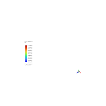
Conjugate Heat Transfer Workflow for Exhaust Manifold
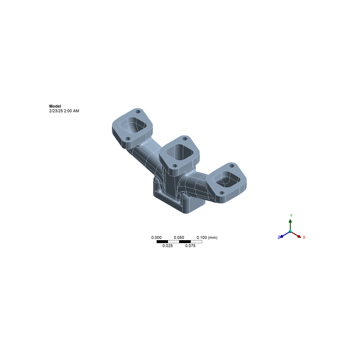
Thermo-mechanical assessment of representative exhaust manifold model
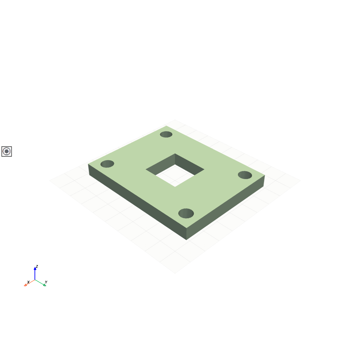
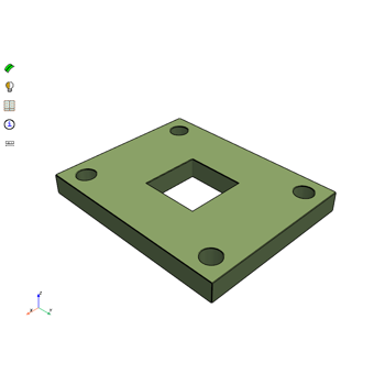
Geometry and meshing workflow#
Below is an example of a geometry and meshing workflow using PyAnsys Geometry and PyPrimeMesh.
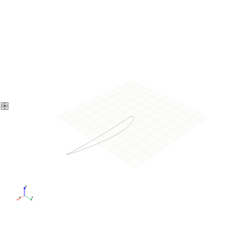
Geometry, meshing and fluids workflow#
Below is an example of a workflow that demonstrates how to create a geometry, mesh it, and run a fluid simulation using PyAnsys. The geometry generated is a NACA airfoil, which is prepared for a fluid simulation. The exported CAD file is then consumed by Ansys Fluent to run a compressible flow simulation over the airfoil.


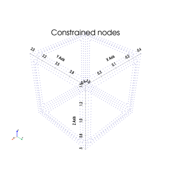
MAPDL and DPF workflow#
This example demonstrates consecutive sub modeling using PyMAPDL and PyDPF. The DPF framework interpolates global model displacements and transfers them as boundary conditions to the local model, enabling efficient global–local coupling with the MAPDL pool.
Maxwell 2D and Lumerical#
Surface electrodes adjacent to grating couplers render an integrated ion trap. This workflow uses Ansys Maxwell to model surface electrodes and Ansys Lumerical to model grating couplers. Using the finite element method, the Maxwell electrostatic solver evaluates the ion trap height. The workflow then passes the coordinates of the ion trap to an optimization algorithm to define the optimal two-dimensional grating coupler design, which focuses the laser beam at the ion trap height.
This article describes the workflow in details.
Q3D and Lumerical#
Surface electrodes adjacent to grating couplers render an integrated ion trap. This workflow uses Ansys Q3D to model surface electrodes and Ansys Lumerical to model grating couplers. Using the boundary element method, the Q3D CG solver evaluates the ion trap height. The workflow then passes the coordinates of the ion trap to an optimization algorithm to define the optimal two-dimensional grating coupler design, which focuses the laser beam at the ion trap height. This workflow is the 3D Boundary Element Method (BEM) counterpart of the Maxwell2D-Lumerical example.
This article describes the workflow in details.

Speos, optiSLang workflow#
Below is an example workflow that demonstrates how to perform an optical lightguide robustness study, set up the robustness workflow, and run an optical simulation using PyAnsys. The lightguide is prepared in Speos and exported as a .speos file. The exported file is processed by pySpeos to run a parametric study, controlled by PyOptiSLang, in order to evaluate the to understand the influence of source power, source position on the lightguide performance, i.e. RMS contrast, average luminance as well as the number of failed regulations
