Note
Go to the end to download the full example code.
Geometry generation#
Generate a NACA airfoil and the surrounding fluid domain using PyAnsys Geometry.
This example demonstrates how to create a sketch, perform modeling operations, and export the file in different formats (in this specific case, FMD). The example also shows how to generate a NACA 4-digits airfoil and the surrounding fluid domain using PyAnsys Geometry. The airfoil is extruded to create a 3D model, and the fluid domain is created as a box around the airfoil.
import os
from pathlib import Path
from typing import List, Union

from ansys.geometry.core import launch_modeler
from ansys.geometry.core.connection import GeometryContainers
import ansys.geometry.core.connection.defaults as pygeom_defaults
from ansys.geometry.core.math import Plane, Point2D, Point3D
from ansys.geometry.core.plotting import GeometryPlotter
from ansys.geometry.core.sketch import Sketch
import numpy as np
Preparing the environment#
This section is only necessary for workflow runs and docs generation. It checks the environment variables to determine which image to use for the geometry service. If you are running this script outside of a workflow, you can ignore this section.
image = None
transport_mode = None
if "ANSYS_GEOMETRY_RELEASE" in os.environ:
    image_tag = os.environ["ANSYS_GEOMETRY_RELEASE"]
    for geom_services in GeometryContainers:
        if image_tag == f"{pygeom_defaults.GEOMETRY_SERVICE_DOCKER_IMAGE}:{geom_services.value[2]}":
            print(f"Using {image_tag} image")
            image = geom_services
            transport_mode = "insecure"
            break
Using ghcr.io/ansys/geometry:windows-24.1 image
Parameters for the script#
The following parameters are used to control the script execution. You can modify these parameters to suit your needs.
# Graphics boolean
GRAPHICS_BOOL = False  # Set to True to display the graphs

# Type of airfoil to generate
NACA_AIRFOIL = "6412"

# Dimensions of the fluid domain
# LENGTH - X-axis
# WIDTH - Z-axis
# HEIGHT - Y-axis
#
BOX_SIZE_LENGTH = 10
BOX_SIZE_WIDTH = 5
BOX_SIZE_HEIGHT = 2

# Data directory
DATA_DIR = os.path.join(os.path.dirname(__file__), "outputs")
Defining the NACA airfoil#
The NACA airfoil is defined by a 4-digit number. The first digit represents the maximum camber in percentage of the chord, the second digit represents the position of the maximum camber in tenths of the chord, and the last two digits represent the maximum thickness in percentage of the chord.
The NACA airfoil is generated using the following formulae:
where:
\(x\) is the x-coordinate of the point,
\(y_c\) is the camber line,
\(y_t\) is the thickness,
\(\theta\) is the angle of the camber line.
The camber line is defined as:
where:
\(m\) is the maximum camber,
\(p\) is the position of the maximum camber.
The thickness is defined as:
where:
\(t\) is the maximum thickness.
The NACA 4-digits airfoil is generated using the following function. The function generates the points of the airfoil using the formulae above and returns a list of points that define the airfoil.
def naca_airfoil_4digits(number: Union[int, str], n_points: int = 200) -> List[Point2D]:
    """
    Generate a NACA 4-digits airfoil.

    Parameters
    ----------
    number : int or str
        NACA 4-digit number.
    n_points : int
        Number of points to generate the airfoil. The default is ``200``.
        Number of points in the upper side of the airfoil.
        The total number of points is ``2 * n_points - 1``.

    Returns
    -------
    List[Point2D]
        List of points that define the airfoil.
    """
    # Check if the number is a string
    if isinstance(number, str):
        number = int(number)

    # Calculate the NACA parameters
    m = number // 1000 * 0.01
    p = number // 100 % 10 * 0.1
    t = number % 100 * 0.01

    # Generate the airfoil
    points = []
    for i in range(n_points):

        # Make it a exponential distribution so the points are more concentrated
        # near the leading edge
        x = (1 - np.cos(i / (n_points - 1) * np.pi)) / 2

        # Check if it is a symmetric airfoil or not
        if p == 0 and m == 0:
            # Camber line is zero in this case
            yc = 0
            dyc_dx = 0
        else:
            # Compute the camber line
            if x < p:
                yc = m / p**2 * (2 * p * x - x**2)
                dyc_dx = 2 * m / p**2 * (p - x)
            else:
                yc = m / (1 - p) ** 2 * ((1 - 2 * p) + 2 * p * x - x**2)
                dyc_dx = 2 * m / (1 - p) ** 2 * (p - x)

        # Compute the thickness
        yt = 5 * t * (0.2969 * x**0.5 - 0.1260 * x - 0.3516 * x**2 + 0.2843 * x**3 - 0.1015 * x**4)

        # Compute the angle
        theta = np.arctan(dyc_dx)

        # Compute the points (upper and lower side of the airfoil)
        xu = x - yt * np.sin(theta)
        yu = yc + yt * np.cos(theta)
        xl = x + yt * np.sin(theta)
        yl = yc - yt * np.cos(theta)

        # Append the points
        points.append(Point2D([xu, yu]))
        points.insert(0, Point2D([xl, yl]))

        # Remove the first point since it is repeated
        if i == 0:
            points.pop(0)

    return points
Start a modeler session#
Start a modeler session to interact with the Ansys Geometry Service. The modeler object is used to create designs, sketches, and perform modeling operations.
# Instantiate the modeler
modeler = launch_modeler(image=image, transport_mode=transport_mode)
print(modeler)
C:\Users\ansys\actions-runner\_work\pyansys-workflows\pyansys-workflows\.venv\Lib\site-packages\ansys\tools\common\cyberchannel.py:201: UserWarning: Starting gRPC client without TLS on localhost:700. This is INSECURE. Consider using a secure connection.
  warn(f"Starting gRPC client without TLS on {target}. This is INSECURE. Consider using a secure connection.")
Ansys Geometry Modeler (0x20653707830)

Ansys Geometry Modeler Client (0x206548c2f90)
  Target:     localhost:700
  Connection: Healthy
  Backend info:
    Version:            0.0.0
    Backend type:       WINDOWS_SERVICE
    Backend number:     N/A
    API server number:  N/A
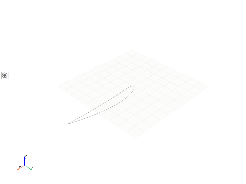
Define the airfoil points#
The airfoil points are generated using the function defined above. The points are used to create a sketch of the airfoil.
# Create the design
design = modeler.create_design(f"NACA_Airfoil_{NACA_AIRFOIL}")

# Create a sketch
airfoil_sketch = Sketch()

# Generate the points of the airfoil
points = naca_airfoil_4digits(NACA_AIRFOIL)

# Create the segments of the airfoil
for i in range(len(points) - 1):
    airfoil_sketch.segment(points[i], points[i + 1])

# Close the airfoil
airfoil_sketch.segment(points[-1], points[0])

# Plot the airfoil
if GRAPHICS_BOOL:
    airfoil_sketch.plot()
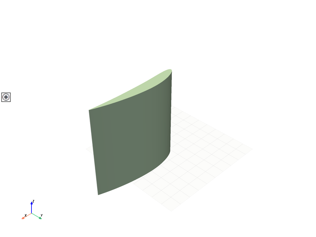
Extrude the airfoil#
The airfoil is extruded to create a 3D model by a given length. This will create a 3D model of the airfoil.
# Extrude the airfoil
airfoil = design.extrude_sketch("Airfoil", airfoil_sketch, 1)

# Plot the design
if GRAPHICS_BOOL:
    design.plot()
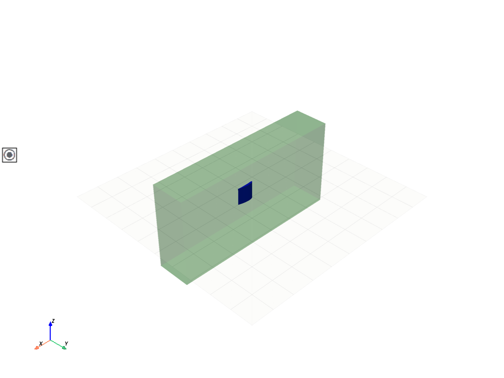
Create the fluid domain#
In this section, the surrounding fluid domain is created as a box around the airfoil.
The airfoil has the following dimensions: - Chord length: 1 (X-axis) - Thickness: depends on NACA value (Y-axis)
The fluid domain will be a large box with the following dimensions: - Length (X-axis) - Width (Z-axis) - Height (Y-axis)
The airfoil will be placed at the center of the fluid domain
Create the sketch
fluid_sketch = Sketch(plane=Plane(origin=Point3D([0, 0, 0.5 - (BOX_SIZE_WIDTH / 2)])))
fluid_sketch.box(
    center=Point2D([0.5, 0]),
    height=BOX_SIZE_HEIGHT,
    width=BOX_SIZE_LENGTH,
)

# Extrude the fluid domain
fluid = design.extrude_sketch("Fluid", fluid_sketch, BOX_SIZE_WIDTH)

# Create named selections in the fluid domain - inlet, outlet, and surrounding faces
# Add also the airfoil as a named selection
fluid_faces = fluid.faces
surrounding_faces = []
inlet_faces = []
outlet_faces = []
for face in fluid_faces:
    if face.normal().x == 1:
        outlet_faces.append(face)
    elif face.normal().x == -1:
        inlet_faces.append(face)
    else:
        surrounding_faces.append(face)

design.create_named_selection("Outlet Fluid", faces=outlet_faces)
design.create_named_selection("Inlet Fluid", faces=inlet_faces)
design.create_named_selection("Surrounding Faces", faces=surrounding_faces)
design.create_named_selection("Airfoil Faces", faces=airfoil.faces)

# Plot the design intelligently...
if GRAPHICS_BOOL:
    geom_plotter = GeometryPlotter()
    geom_plotter.plot(airfoil, color="blue")
    geom_plotter.plot(fluid, color="green", opacity=0.25)
    geom_plotter.show()
Export the design#
The design is exported to a file in PMDB format. The PMDB file can be used in Ansys Fluent to generate the mesh, since it contains the geometry and the named selections.
Design saved to C:\Users\ansys\actions-runner\_work\pyansys-workflows\pyansys-workflows\geometry-mesh-fluent\outputs\NACA_Airfoil_6412.pmdb
Close session#
When you finish interacting with your modeling service, you should close the active server session. This frees resources wherever the service is running.
# Close the server session.
modeler.close()
WARNING - localhost:700 -  design - close - Design NACA_Airfoil_6412 could not be closed. Error: Geometry service connection terminated: Object reference not set to an instance of an object..
WARNING - localhost:700 -  design - close - Ignoring response and assuming the design is closed.
Total running time of the script: (1 minutes 0.934 seconds)