Note
Go to the end to download the full example code.
Geometry generation#
This example shows how to generate a simple PCB using PyAnsys Geometry via the Ansys Geometry Service. The example demonstrates how to create a sketch, perform modeling operations, and export the file in different formats (in this specific case, PMDB).
import os
from pathlib import Path

from ansys.geometry.core import launch_modeler
from ansys.geometry.core.connection import GEOMETRY_SERVICE_DOCKER_IMAGE, GeometryContainers
from ansys.geometry.core.designer import DesignFileFormat
from ansys.geometry.core.math import Plane, Point2D, Point3D, UnitVector3D
from ansys.geometry.core.misc import DEFAULT_UNITS, UNITS
from ansys.geometry.core.sketch import Sketch
Preparing the environment#
This section is only necessary for workflow runs and docs generation. It checks the environment variables to determine which image to use for the geometry service. If you are running this script outside of a workflow, you can ignore this section.
image = None
if "ANSYS_GEOMETRY_RELEASE" in os.environ:
    image_tag = os.environ["ANSYS_GEOMETRY_RELEASE"]
    for geom_services in GeometryContainers:
        if image_tag == f"{GEOMETRY_SERVICE_DOCKER_IMAGE}:{geom_services.value[2]}":
            print(f"Using {image_tag} image")
            image = geom_services
            break
Using ghcr.io/ansys/geometry:windows-25.1 image
Parameters for the script#
The following parameters are used to control the script execution. You can modify these parameters to suit your needs.
GRAPHICS_BOOL = False  # Set to True to display the graphics
OUTPUT_DIR = Path(Path(__file__).parent, "outputs")  # Output directory
Start a modeler session#
Start a modeler session to interact with the Ansys Geometry Service. The modeler object is used to create designs, sketches, and perform modeling operations.
modeler = launch_modeler(image=image)
print(modeler)
Ansys Geometry Modeler (0x1be0e7abfb0)

Ansys Geometry Modeler Client (0x1be0e3c4d10)
  Target:     localhost:700
  Connection: Healthy
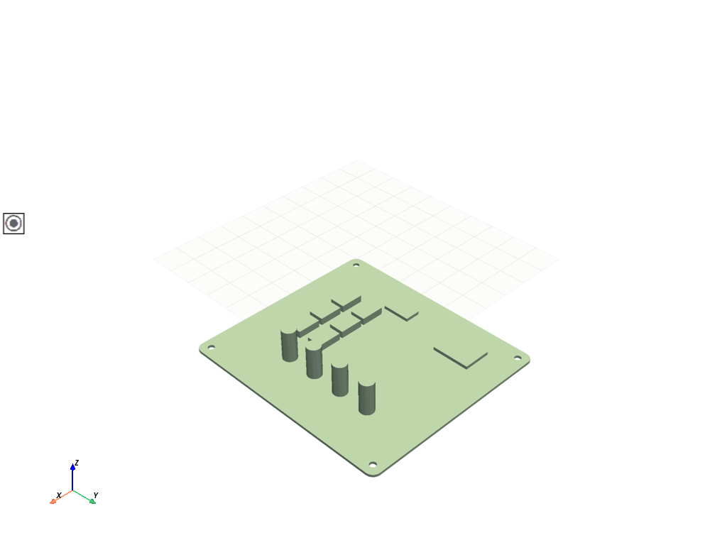
Create PCB geometry#
# Define default length units
DEFAULT_UNITS.LENGTH = UNITS.cm

# Define the radius of holes in pcb
pcb_hole_radius = 1

# Create PCB Substrate
sketch_substrate = Sketch()
(
    sketch_substrate.segment(Point2D([5, 0]), Point2D([122, 0]))
    .arc_to_point(Point2D([127, 5]), Point2D([122, 5]))
    .segment_to_point(Point2D([127, 135]))
    .arc_to_point(Point2D([122, 140]), Point2D([122, 135]))
    .segment_to_point(Point2D([5, 140]))
    .arc_to_point(Point2D([0, 135]), Point2D([5, 135]))
    .segment_to_point(Point2D([0, 5]))
    .arc_to_point(Point2D([5, 0]), Point2D([5, 5]))
    .circle(Point2D([6.35, 6.35]), radius=3.94 / 2)
    .circle(Point2D([127 - 6.35, 6.35]), radius=3.94 / 2)
    .circle(Point2D([127 - 6.35, 140 - 6.35]), radius=3.94 / 2)
    .circle(Point2D([6.35, 140 - 6.35]), radius=3.94 / 2)
)
substrate_height = 1.575
plane = Plane(
    origin=Point3D([0, 0, substrate_height]),
    direction_x=[1, 0, 0],
    direction_y=[0, 1, 0],
)

# create IC
sketch_IC = Sketch(plane)
sketch_IC.box(Point2D([62 / 2 + 7.5, 51 / 2 + 5]), 15, 10)

# create capacitor sketch
sketch_capacitor = Sketch(plane=plane)
sketch_capacitor.circle(center=Point2D([95, 104]), radius=4.4)

# create ic
sketch_ic_7 = Sketch(plane=plane)
sketch_ic_7.box(Point2D([25, 108]), 18, 24)

# create ic
sketch_ic_8 = Sketch(plane=plane)
sketch_ic_8.box(Point2D([21, 59]), 10, 18)
<ansys.geometry.core.sketch.sketch.Sketch object at 0x000001BE0E902CC0>
Modeling operations#
Now that the sketch is ready to be extruded, perform some modeling operations, including creating the design, creating the body directly on the design, and plotting the body.
# Start by creating the Design
design = modeler.create_design("pcb_design")

# Create all necessary components for pcb
component = design.add_component("PCB")
component.extrude_sketch("substrate", sketch_substrate, distance=substrate_height)
ic_1 = component.extrude_sketch("ic-1", sketch_IC, distance=4.5)

ic_2 = ic_1.copy(parent=component, name="ic-2")
ic_2.translate(direction=UnitVector3D([1, 0, 0]), distance=17)

ic_3 = ic_1.copy(parent=component, name="ic-3")
ic_3.translate(direction=UnitVector3D([0, 1, 0]), distance=17)

ic_4 = ic_2.copy(parent=component, name="ic-4")
ic_4.translate(direction=UnitVector3D([1, 0, 0]), distance=17)

ic_5 = ic_2.copy(parent=component, name="ic-5")
ic_5.translate(direction=UnitVector3D([0, 1, 0]), distance=17)

ic_6 = ic_5.copy(parent=component, name="ic-6")
ic_6.translate(direction=UnitVector3D([1, 0, 0]), distance=17)

ic_7 = component.extrude_sketch("ic-7", sketch=sketch_ic_7, distance=2)
ic_8 = component.extrude_sketch("ic-8", sketch=sketch_ic_8, distance=2)

capacitor_1 = component.extrude_sketch("capacitor_1", sketch_capacitor, distance=20)
capacitor_2 = capacitor_1.copy(parent=component, name="capacitor_2")
capacitor_2.translate(direction=UnitVector3D([0, 1, 0]), distance=-20)
capacitor_3 = capacitor_1.copy(parent=component, name="capacitor_3")
capacitor_3.translate(direction=UnitVector3D([0, 1, 0]), distance=-40)
capacitor_4 = capacitor_1.copy(parent=component, name="capacitor_4")
capacitor_4.translate(direction=UnitVector3D([0, 1, 0]), distance=-60)

# Create named selections
for body in component.bodies:
    design.create_named_selection(name=body.name, bodies=[body])

# Plot the the entire geometry
if GRAPHICS_BOOL:
    design.plot()
Export the design#
Once modeling operations are finalized, you can export files
in different formats. For the formats supported by DMS, see the
DesignFileFormat class in the Design module documentation.
# Export files in PMDB format for Mechanical.
OUTPUT_DIR.mkdir(exist_ok=True)
download_file = Path(OUTPUT_DIR, "pcb.pmdb")
design.download(file_location=download_file, format=DesignFileFormat.PMDB)
Close session#
When you finish interacting with your modeling service, you should close the active server session. This frees resources wherever the service is running.
# Close the server session.
modeler.close()
Total running time of the script: (0 minutes 57.358 seconds)